
Working on Interrupts
- rehsd

- Nov 14, 2022
- 4 min read
Updated: Nov 15, 2022

Current Status: RESOLVED
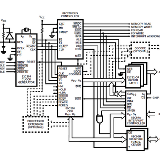
I am currently working to get interrupts running on my 286 system. I am starting with a simple low-to-high signal for the interrupt source, coming from my PS/2 keyboard circuit. This is going to my PIC (priority interrupt controller - Harris 82C59A). Out of the PIC, I am not seeing any changes on INT (to INTR on the 286). Possible causes could be code or something with my design. Looking at the basic design below, this shows connecting INT on the PIC to INTR# on the 286, and INTA# on the Bus Controller to INTA# on the PIC.

Here is my current build configuration:

Full Schematic
For I/O mapping, I am using 0x0010 for the PIC controller, along with 0x0012. I have A1 from the address bus connected to pin A0 on the PIC.
The current assembly code that I am using is available at keyboard.asm. I am using NASM to generate a binary file. The associated listing file is available at keyboard.lst, and a modified listing file with the ROM starting address (0x80000) added to the address column (simply for ease of reading) is available at keyboard_adjusted.lst.
I also recorded a debug session. I need to review this in detail yet, but the log is available at 80286_run.log. The "Enable:" section to the far right of the log will indicate when IO to the PIC is active, showing "IRQ." As an example, filtering the output down to just when the PIC is enabled (i.e., when writing config), the following address and data values are present:
0x:000010:0013
0x:000012:0008
0x:000012:0001
0x:000012:0000
Update: I am able to write OCW1 (using 0x00D0) to the PIC and read back that value from the PIC. I have verified all signals logged in the Windows application for the PIC write operation match values measured at the PIC itself.
If anyone can spot issues, please let me know. Interrupts are not working yet, so there are issues. :)
Data Bus Transceiver Enable
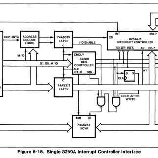
One possibility is that I am running into an issue with timing on my data bus, and when I am enabling the transceiver output. Below, the first graphic is from my current schematic (left). The other two are alternate versions from Intel and Harris. Intel's Figure 15-5 (right) has more complicated OE# logic for the data transceivers than that in Harris's Figure 31 (middle) -- and both of which include more than my current setup. I am going to experiment with the OE# on my data transceivers next. I think I am going to try the Harris setup first. If no luck, I may then try the Intel setup. The Harris version appears to require me to change the config of the PIC to buffered mode. The Intel version mentions the requirement of one wait state. If you have thoughts on this, please let me know.


To perform some basic testing on data writes to the PIC, I wrote a simple routine that writes a bit to a PIC register, reads it back, rotates the bit, and repeats.
pic_register_test:
mov al, 0x01
.testloop:
out PICM_P1, al
mov al, 0x00 ; Clear al
in al, PICM_P1 ; Retrieve al from register
out 0x00A0, al
rol al, 1
jmp .testloop
ret ; Will never get here
I then ran the system with a processor clock of ~125 Hz, recording the debug session. As far as I can tell, everything looks good. The values read back from the register match the values written to the register.

I then tested with the following procedure with a 4 MHz processor clock.
pic_register_test2:
mov al, 0x01
.testloop2:
mov dl, al
out PICM_P1, al
mov al, 0x00 ; Clear al
in al, PICM_P1 ; Retrieve al from register
cmp al, dl
jnz .fail
out 0x00A0, al
rol al, 1
jmp .testloop2
.fail:
mov al, 'F'
call lcd_data_write
jmp .testloop2
ret
No errors were registered, so I manually pulled wires for data lines at the PIC (while the system was running) to generate a failure (to verify my test code was working correctly). With that, I was able to generate a failure ("F" written to the LCD).
My interpretation is that the data bus is working fine.
Resolved!

Well, I hope this doesn't shock anyone. It was a very silly error on my part 🙄, and I was able to resolve the issue. At some point, I believe I modified my schematic to shift some pins around for readability on the schematic. Unfortunately, as I was later referencing the schematic, my brain was processing connections by the location on the IC on the schematic, and not the pin number marked on the pin on the IC. I was using pin 15 for INT when I should have been connecting to pin 17 for INT!!!!! Arggghh! Well, I learned a bunch along the way at least. 🙂

Thank you, everyone, for all your help!!
Feedback / Suggestions / To Do
[COMPLETE] I am setting single mode. With this, I should not be setting CW3, but I am currently setting CW3. I will remove the call to set CW3. Thank you Tamsin for the suggestion! Update: I have removed the call to CW3. Now to find the next issue (not working yet).
The batch of PICs I am using are labelled as Harris CP82C59A-5 (8921 A3175). I have ordered a different batch of PICs for testing. I find it unlikely my current PICs are faulty, but I should verify that.
Datasheets
References
The 80x86 IBM PC And Compatible Computers: Assembly Language, Design, and Interfacing, 4th Ed., Mazidi and Mazidi
Programming the 8259 PIC: A Tech-Tip Example and Boilerplate
Intel 80286 Hardware Reference Manual (pages 5-20+)
Intel Application Note AP-59: Using the 8259A Programmable Interrupt Controller


Comments