
Walkthrough: PC Interface for Eater 8-bit CPU
- rehsd

- Feb 17, 2022
- 4 min read
Last year, I had completed my 8-bit CPU, based on Ben Eater's video series. At the end of this project, I added a couple of Arduinos -- one to display the clock speed and another to support updating RAM and reading the bus, control bits, and output. I also built a Windows application to interface with it.
I've received a few questions about this setup. I thought it might be helpful to post a walkthrough of the Arduino setup, along with the Windows application. It has been a while since I've worked on this, so I've had to dust off both the board and my memory. :)
The Hardware
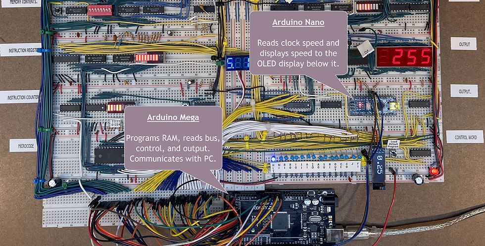
For the most part, the board you see below followed Ben's design. I had tweaked some of the clock signal distribution based on some issues I was having, along with using LED bar graphs instead of individual LEDs. I added a voltage display (due to the multiplexing, the camera doesn't pick it up very well).

I added an Arduino Nano to read and display the clock speed, along with passing the information to the Arduino Mega. The Mega communicates to the PC and supports programming of the RAM, and reading the bus, control bits, and output of the 8-bit CPU. Note: If I was to do this project again, I would use an Arduino Due instead of the Mega. The communication speed capabilities of the Due (to the PC) are significantly better. However, the Due, which uses 3.3V, would require voltage level shifting to deal with the 5V signals.
Here's how I connected the Arduinos:
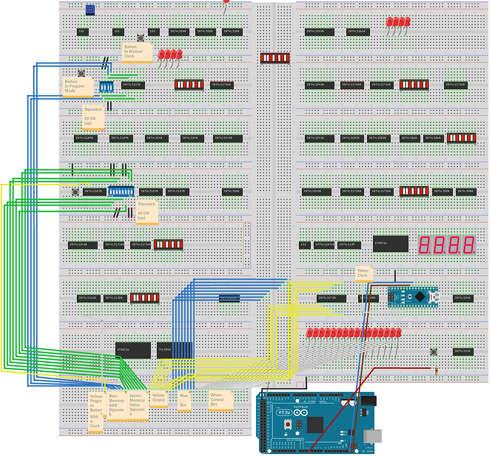
The Arduino Mega project includes the following definitions for connecting the signals to the Mega:

The SDA and SCL pins on the Mega are connected to A4 and A5, respectively, on the Nano. I have 1K pull-up resistors on the SDA and SCL lines. The Load Default Program button is connected through a resistor (I happen to be using an 8.2K resistor) to ground and to pin 3 on the Mega. The small OLED display is connected to GND and VCC, along with SCL and SDA to the Nano (A5 and A4, respectively). The Nano is powered off the 8-bit CPU power rails (Nano pins GND and 5V). The system clock is connected to D2 on the Nano. The Mega is powered from USB going to the PC. In addition to the connections listed above in the definitions, don't forget to connect the Mega GND to the 8-bit CPU ground.
The Software
With the hardware connected, we can now take a look at the code.
Arduino Nano
The Nano code is fairly simple. It attaches pin 2 to the clock signal and when the clock signal changes, calculates the clock speed. The clock speed is displayed on the OLED display and sent via I2C to the Mega.

Arduino Mega
The Mega code essentially consists of these routines:

receiveEvent() catches clock value updates from the Nano.
buttonLoadDefaults_ISR() runs when the Load Default Program is pressed and calls setRAM().
loop() is used to present the user interface via serial terminal.
onClock() reads values from the bus, control, and output -- and sends to the serial output.
setRAMCustom() takes processes RAM values submitted via serial and updates the RAM of the 8-bit CPU accordingly. It calls setSingleRAM().
setRAM() contains pre-programmed defaults for RAM.
setSingleRAM() updates a single RAM address.
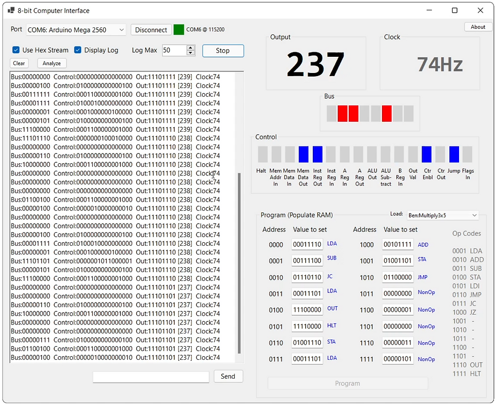
When running, the Mega can be access from a terminal, or from a Windows forms applications (which connects to the terminal interface).
PC: Windows Forms
The Windows forms application wraps the Mega terminal interface and allows programming and monitoring, including quickly loading pre-saved 'programs.'
The Winforms code consists of these routines:

ConnectButton_Click() establishes the serial connection to the Mega.
MyPort_DataReceived handles incoming data from the Mega.
UpdateClockDisplay() updates the clock frequency displayed on the form.
UpdatedOutputDisplay() updates the output value displayed on the form.
UpdateControlDisplay() updates the control value indicators on the form.
UpdateBusDisplay() updates the bus value indicators on the form.
SendButton_Click() sends individual, manually entered commands to the Mega.
UpdateOpCodeLabel() updates the form to show the opcode friendly name when you enter numeric opcodes.
StartMonitorButton_Click() starts live monitoring.
ProgramRAMButton_Click() programs the CPU based on values in the form.
Pre-saved 'programs' can be placed in the App.config file of the Winforms application. These can then be loaded in the Winform at runtime.

Operation
Control of the 8-bit CPU can be done directly from a serial terminal interface, connecting to the Mega. From the terminal, you can program defaults (based on how you have it coded in the .ino file for the Mega), program custom values (specifying binary values for all sixteen memory addresses... in one big string, lol), and monitor the CPU with binary or hex output. To use the Arduino to program the 8-bit CPU, on the CPU:
Set clock mode switch to manual
Set memory program mode switch to enable
Set RAM value dip switches to UP (on)
Set RAM address value dip switches to UP (on)
To use the Arduino to monitor the 8-bit CPU, on the CPU:
Set clock mode switch to automatic
Set memory program mode switch to disable
Here's the Windows forms application in action:
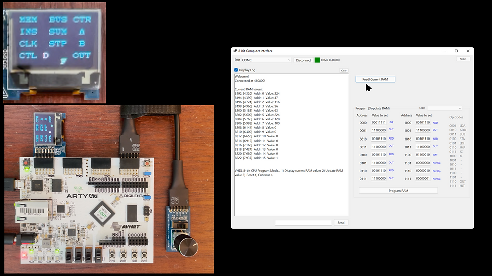
Source Files
Questions, Suggestions?
I'm likely missing some important details above. And, by no means is the above meant to show the right/best way to do things -- it's just how I did it at the time. If you have questions or suggestions, please let me know!


excellent walkthrough .. the best I have ever seen !
dave