Start to an 80286 System
- rehsd

- Oct 10, 2022
- 3 min read
Updated: Oct 18, 2022
I am spinning up a new project -- a breadboard-based 80286. I have not worked with x86 processors from a design perspective before. The most I have done is plug one into a socket on a motherboard as part of a standard PC assembly process. So, this will be interesting. I have lots to learn, and I anticipate plenty of challenges along the way.

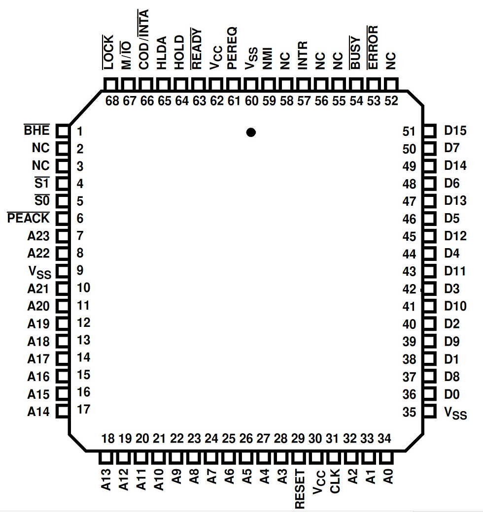
I am starting with a Harris 80C286-25, which has pinouts shown to the right. The processor has 24 address lines and 16 data lines. I believe signals such as S1#, S0#, COD/INTA#, and M/IO# will quickly become important, and I have work to do to understand how to properly leverage these signals.
This is a PLCC-68 IC, so I designed a simple PCB to make it breadboard friendly.

In the Harris documentation, a basic configuration is provided. This is what I will try to complete. I have parts on order (clock generator, bus controller, latches, interrupt controller, and transceivers). It may be three to four weeks before I receive these parts.

All I have completed so far is getting the processor powered up and feeding it NOPs.
Postscript
Zxborg had a nice suggestion to incorporate the LEDs into the PCB rather than use breadboard space. Below is version 1.1 of the PCB. The PCB can be ordered as a single PCB, but it should easily snap in half. The upper part can be stacked on the lower CPU portion. I also increased the number of VCC and GND pins going into the PCBs. With this design, I will get to practice my surface mount soldering skills (oven or hot plate).

PCB source files and Gerber files posted to x86/286-related at main · rehsd/x86 (github.com).

As an update to the ROM addressing approach I took in the above videos, I did find a diagram of Intel's approach to the high and low ROMs. The following figure is from Intel's 80286 Hardware Reference Manual. This configuration assumes the use of the 82C288 Bus Controller. (I have a Bus Controller IC on order, but it may be a few weeks before I get it.) Essentially, the address bits are shifted one, where A0 is not connected to the ROMs.
The manual also indicates that the 80286 only accepts the appropriate byte, so technically, I can read the full word all the time and the processor will use just the part that it needs (high or low byte on the data bus). However, this might be confusing as I look at my debug LEDs, so I intend to keep the CE# approach I have now (at least for the time being). In the diagram below, OE# is controlled by the memory read command from the Bus Controller.
I am reading through the 80286 Hardware Reference Manual, and I just realized that the processor can only access 1 MB of memory addresses when in Real-Address mode. Given this, I think I need to update my ROM and RAM decode. I plan to use ROM for the top half of the 1 MB address space, and the RAM for the bottom half. This also means that I will be wasting half of the ROM capacity and half of the RAM capacity.
Also, Dagobert Krikelin pointed out an error in my use of S1 that would have caused simultaneous OE# active (output) and WE# active (write) states (thanks, DK!).
Here is an updated schematic with my current thoughts.

With some adjustments to my RW# and OE# logic for the RAM, and with some help from r/ASM to get my assembly JMP from RESET to TOP to work, it looks like my RAM writing and reading might be working. I have more testing to do. At this point, my wires are getting pretty messy, and I have a decent feel for the decode logic. I think I am going to shift my decode logic over to a PLD or PSoC.
The PSoC that I am using is a Cypress CY8C5888LTI-LP097, packaged in a CY8CKIT-059.


Love that you’re blogging this journey 🎒