
65816 PC Build - Lessons Learned (running post)
- rehsd

- Mar 14, 2022
- 5 min read
Updated: Apr 24, 2022

I will update this post as I work on my 65816 PC and identify mistakes in my 65816-related PCBs, so check back to see how they all pile up. :)
March 13
Ordered PCBs.
March 14

I haven't even received my PCBs, and I have already identified a gigantic error. Ugh. Today, I was working on a pair of PCBs to make an ISA extension cable, so that I can connect ISA cards on my workbench to my 65816 ISA slots. In the process, I realized that the design component I used in EasyEDA for the ISA slot is completely wrong! While the edge connector component is correct, the slot component has two banks of pins swapped (ISA bank D was swapped with part of bank A). I didn't catch this until I placed both components in the same PCB and saw that
connections were crossing over. While the component was incorrect, it was my mistake for not completely validating this component. This will require a re-spin of the motherboard. While I was planning on a second version with adjustments, this is a bit more than an adjustment -- and way sooner than I was expecting. My plan at this point is to do some serious bodge work and have a corrected slot connected to the motherboard to validate other aspects of the system. This is going to be ugly.

To help, I ordered a couple of PCBs to let me go from an ISA edge connector to a slot connector. I can adapt the wiring between the two. Also, I can use standard 50-pin ribbon cable for ISA slot extensions, allowing me to test boards outside of the system case.
March 24
PCBs received.

ATX Case Fitment
The motherboard standoffs fit well. The bracket mounting holes in the expansion cards need to be adjusted. I had the spacing of the top hole at 85mm from the bottom of the ISA edge connector, when it should have been 85mm from the center of the bottom hole. Also, the holes should be shifted towards the inside of the card by approximately 4mm. The ISA slots could possibly be shifted on the motherboard to better align with the ATX case, but it's good enough for my needs.


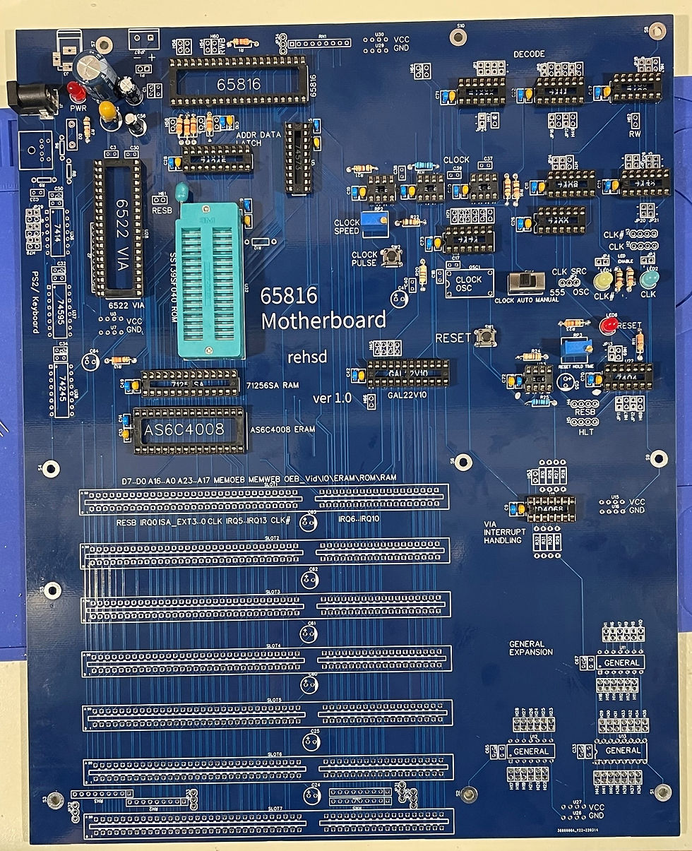
Motherboard Population
U6, if placed in a DIP socket, may possibly interfere with the ROM ZIP socket handle. Either go without the socket, move the ZIF down (towards the ISA slots) by 4mm, or shorten the handle (or use a ZIF with a shorter handle). For this initial build, I just shortened the ZIF handle.
March 25
Core 65816 is running! I connected an ISA extension board to the bottom ISA slot location with wiring so that I could correct the issue in the pinout on the motherboard. I plugged in one of my ISA LCD add-in boards and pulled signals from it for the Arduino logging. This logging was done with the 555 circuit (i.e., slower clock speeds). I then tested 65816 clock speeds up to 14 MHz (with success!). I am very happy with the results so far.

Honestly, I was a bit surprised it was running perfectly fine at 14 MHz. I was hoping for 8 to 10 MHz. I'm not going to complain!

I am already very much appreciating the ISA slot connector. Now, I can disconnect the Arduino debugger by simply pulling the add-in card out of the ISA slot. So easy...
March 26
I have added Extended RAM and confirmed basic functionality of ROM, RAM, Extended RAM, and I/O. In the following video. you can see some simple test code, an overview of my addressing, and the logged output. In the logged output, OEB shows which device is being accessed.
March 28
I have essentially completed the motherboard population and testing of all key features (e.g., clock circuit, reset circuit, ROM, RAM, extended RAM, VIA, PS/2 keyboard input circuit, interrupt handling, address decoding, etc.). I have connected a 1602 LCD for testing.
I'm running the processor in native mode with 16-bit registers enabled. While this isn't always the most efficient, I'm forcing myself to learn how to code with 16-bit. In the future, I'll see if I can switch back and forth between 8-bit and 16-bit modes in the code, using the optimal mode for the task at hand.

VGA Add-in Card Buildout
I have started a separate post to share the buildout of my VGA add-in card. See VGA Add-in Card for My 65816 PC.
April 4
I have ordered version 1.1 on the motherboard, with corrections made to the ISA slot pinout, along with other minor corrections and a few additions. Updated design files have been posted to rehsd/PC-65816: PC based on 65816 (github.com).

April 11
Version 1.1 PCB received. I really hope the ISA slot pinout is correct on this version. :)

April 12
I have assembled the 1.1 version of the motherboard. The video card did not work initially, but I was able to track down the issue to a production problem with one of the motherboards. It looks like one of the pads for an ISA slot didn't come out quite right, and it failed to connect the address line to the rest of the ISA slots. I ran a short bodge wire, and all is good. The other PCBs I received don't appear to have the issue. So, at this point, I have the full system running, with animated video content. The bus signals don't look as clean as I'd like to see it, so I have some work to do yet. I have ordered some bus resistors with different values. Right now, I'm using 10K pull-up & pull-down resistors; I think these are too large. Also, I want to experiment with different ICs to see if I can improve system speed.
April 13
Working to improve speeds: 65816: Working to Improve Speeds.
April 14
The system is now running at 14 MHz, with 320x240 video output -- and it's working well. I have posted updated schematics and PCB design files to rehsd/PC-65816: PC based on 65816 (github.com).
The specific ICs I am using have been updated on the schematic. For the 14 MHz clock, the following are working well for me:
W65C816S6TPG-14
W65C22S6TPC-14
SST339F040-70-4C-PHE
IDT71256-SA15TPG
ASC6C4008-55PIN
SN74F260N
SN74AC14N
CD74AC00E
GAL22V10D-10LP
My Key Takeaways
Do not assume that components pulled from EDA tool libraries were built correctly. Always validate.
...
My To Do List
Update ISA slot pinout on motherboard. ✔
Shift top bracket mount hole on expansion cards to be 85mm from the center of the bottom hole, not 85mm from the bottom of the edge connector. Shift mounting holes inward by 4mm.
Move ROM ZIF socket down 4mm. ✔
C59 is a reset cap, not a filtering cap for U22. Move on PCB and add a filtering cap to U22. Same with C54 (part of reset U23). ✔
R13 should be near the 65816. ✔
C64 should be near ISA slot 1. ✔
Improve silkscreen placement for component identifiers.
Renumber all components to be sequential from upper left to lower right (or at least better organized than they are now).
Could consolidate the four 555's down to a pair of 556's (or a single 558).
I'm missing an "R" on the VGA card output silkscreen (BBGGGRRR).
The VIA LCD add-in card's output for the LCD has labels that are not on the silkscreen layer (and are consequently unreadable). Plus, all the data lines were labeled Data0.
The filtering caps on the ISA extender cards are backwards (if using polarized caps). Swap direction of these caps. (How does this happen?! lol)
Add RWB signal to ISA bus. ✔
Silkscreen for U38 is incorrect. It is a 74595, not 74245. ✔
Change silkscreen symbol on D2 (or any other diodes) to show polarity. ✔
Add supplemental power connectors for add-in cards near ISA slots. ✔
Wider traces for bus?


Which system to you plan on running this? Could it run IIgs software or will it be primarily targeted as a C64 or a complete custom OS?
Do you plan to make it license free so others can download gerber files, source components and build their own vintage-old machines?