
MCU (and some FPGA) Fun
- rehsd

- Jan 17, 2024
- 4 min read
Updated: Apr 5, 2024
I am starting to experiment with different microcontrollers (MCUs). I am hoping to learn about 8-bit, 16-bit, and 32-bit MCUs -- from a variety of vendors. My current plan is to work through this list of MCUs that I have:
NXP MC9S08GT32CFB (8-bit)
Texas Instruments MSP430F167IPM (16-bit)
Renesas R5F100FFGAFP (16-bit)
NXP MC9S12A64CPVE (16-bit)
Texas Instruments TMS320F28035PAGT (32-bit)
Microchip ATSAMG55J19B-MU (32-bit)
Cypress PSoC 5LP CY8C58LP Family (32-bit)
Maybe some FPGAs at this point (not MCUs, of course)
Lattice iCE40
If I get bored, I also have these on hand:
Microchip PIC16F883-I/SO
Texas Instruments MSP430F5310IRGCR (VQFN 64, 0.5mm pitch)
As I work through these, I will update this post.
NXP MC9S08

I am using CodeWarrior v11.1 Special Edition to develop in C. For a programmer, I am using a USBDM programmer. For my specific installation, I am running Windows 11 and took the following steps to setup my environment:
Installed CodeWarrior v11.1 Special Edition.
Installed the USBDM drivers. I downloaded drivers from USBDM/Version 4.12.1/Drivers at SourceForge.net.
Installed USBDM software. I downloaded the software from USBDM/Version 4.10.6/Software at SourceForge.net.
With the above completed, I created a new project in CodeWarrior for my specific MCU. I can write and compile C code, program the MCU flash, and debug the hardware. I have found that exiting CodeWarrior's flashing or debugging often loses connection to the USBDM, so I will need to figure out if this can be improved. For example, if I enter a debug session, I am not able to reprogram the MCU or restart the debug session without restarting CodeWarrior. As a workaround for rapid developing and flashing, I build the code in CodeWarrior and use the HCS08 Flash Programmer application that comes with the USBDM software linked above; this combination is working well.
Additional Resources
Texas Instruments MSP430F167IPM
Future work...

Additional Resources
Datasheet: MSP430F167IPM
MSP430 Hardware Tools User's Guide (Rev. AH) (ti.com) - includes info on MSP-FET430UIF debugger / programmer
MSP-FET430 FLASH Emulation Tool (for use with IAR Version 3.x) User's Guide (Rev . C) (conrad.com)
MSP430F5529 LaunchPad Development Kit (MSP-EXP430F5529LP) User's Guide (Rev. D) (ti.com) (includes dev PCB schematic)
Renesas R5F100FFGAFP
Future work...

Additional Resources
NXP MC9S12A64CPVE
Future work...
Texas Instruments TMS320F28035PAGT
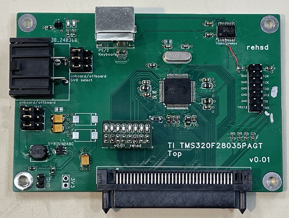
I'm just starting to work with this MCU. So far, I am able to compile a project and program/debug the MCU. For some reason, the programming does not persist after a power cycle, so I must not be doing something correctly on the programming side of things or on the boot mode selection; most likely, it's how I am setting up the project and/or programming the device.
Steps to setup development environment:
Install C2000Ware.
Install Code Composer Studio (not Theia) for Windows.
Install C2000 Compiler
Run Code Composer Studio and create a new project.
To open a sample project:
You can use Resource Explorer to find examples. You can also use the Import Wizard. From the New CSS Project Windows, click Import Wizard.
Change the Select search directory to the following folder within the C2000Ware installation location: C2000Ware_5_01_00_00\device_support\f2803x\examples. In Discovered projects, check "Example_2803xLEDBlink [c28/timed_led_blink]."
Check "Automatically import referenced projects..." and "Copy projects into workspace."
Click Finish.
In Project Explorer, open Example_2803xLEDBlink.c. Update as desired (e.g., change which GPIO is used for LED).
Project\Properties, set Variant and core to: 2803x Piccolo, TMS320F28035, C28xx. Set Connection to Texas Instruments XDS100v2 USB Debug Probe and click Verify to ensure it works (this requires the probe be connected to the MCU PCB and power applied to the PCB).
Project\Build All.
Run\Debug.
To create a new, blank project:
Target: Piccolo\TMS320F28035.
Connection: Texas Instruments XDS100v2 USB Debug Probe.
To write the program in flash for standalone operation (i.e., no debugger and the MCU boots off its internal flash), follow Lab 10: Programming the Flash from F2803x Workshop (ti.com). I continued with the project from the first video.
I started with the LED sample project (above).
I replaced the linker command file with the file from Lab 10, naming it 28025_RAM_lnk2.cmd. This file has updates to the memory blocks and code sections to move the program to flash memory. See FLASH_ABCDEFGH.
See notes about InitPieCtrl() and Flash.c on page 10-16 of the Lab 10 manual. For my project the flash support was already in DSP2803x_SysCtrl.c and PIE support in DSP2803x_PieCtrl.c.
In my main() function in Example_2803xLEDBlink.c, I added a call to memcpy to copy the secureRamFuncs to CSM secured RAM. I then called InitFlash().
I added Passwords.asm to my project, from the Lab 10 files.
DSP2803x_CodeStartBranch.asm was already in my project to handle the code start branch.
Additional Resources
Microchip ATSAMG55J19B-MU
Future work...
ST STM32F417VET6
Future work...
Cypress PSoC 5LP CY8C58LP Family

After getting the CY8C5888LTI-LP097 working in the above video, I then assembled a PCB with the CY8C5888AXQ-LP096. I plan to use this larger PSoC on my 486 DX2 build.
Additional Resources
Lattice iCE40
I have moved content from this section to Lattice iCE40 FPGA Journey (rehsdonline.com).
Hello Dear, It's pleasure to connect with you, could you please share the download link of HCS08 Flash Programmer application to the following email address: sr985504@gmail.com