
ISA Slot & Edge Wear
- rehsd

- Aug 15, 2022
- 2 min read
Updated: Aug 19, 2022
I have been using ISA slots and ISA edge connectors on many of my recent builds. I was asked some great question about durability (thanks, u/TiiXel!). How quickly will the slots or edge connectors wear out? In the following video, I perform some basic testing -- up to 200 insertions.
Short answer: After some quick testing, I do not have any concerns with ISA slot or edge wear for my homebrew projects.
After 200 inserts, this was the worst pad I could find:


I tested soldering this worn pad. It soldered without issue.

My the tested PCB above:
-Manufacturer: JLCPCB
-Copper weight: 1 oz.
-Surface finish: HASL (with lead)
Additional Testing
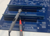
A nice suggestion came in from a YouTube viewer. Russell suggested measuring resistance. In the video, I simply checked for continuity. I setup a new test, adding two ISA slots connectors, and I used two new add-in PCBs. I measured resistance between matching pins of the two add-in PCBs, as shown in the images below. I measured resistance of all pins that were routed on the PCBs (card and motherboard). I measured values at 1, 20, 100, and 200 insertions. Measurements were done with a Siglent SDM3045X digital multimeter with room temperature of approximately 73F (23C) and humidity of approximately 50%.


When new, most connections measured between 0.23Ω and 0.25Ω. VCC and GND had multiple connections and measured between 0.07Ω and 0.12Ω. After 20 insertions, no statistically-relevant differences were measured. After 100 insertions, most connections measured the same; however, a handful of connections increased by 0.10Ω to 0.22Ω. After 200 insertions, most connections measured between 0.24Ω and 0.27Ω, with a subset increasing by as much as 0.34Ω. Below are images of the cards after 200 insertions. Also, I summarized some key data in the table below.


# Insertions | Average Ω | % Increase Ω (from new) | Largest Single Increase Ω (from new) |
0 | 0.22 | | |
20 | 0.21 | -3% | 0.04 |
100 | 0.24 | 10% | 0.22 |
200 | 0.30 | 38% | 0.34 |
This data is from a single set of tests, up through 200 insertions. Ideally, I would repeat this entire set of tests, with new hardware each time, another 20 times (which I am not going to do 🙂). One thing to consider in this latest test is that a pair of cards were inserted, and the increase in resistance is based on two cards being worn. Possibly, that implies that a single card will see half of the impact shown in the table above.
Also, the ISA slots begin to loosen up a bit after 100 insertions and could result in a diminished connection to the add-in card. I do not believe this is a concern, but it could be tested by using worn add-in cards in brand new ISA slots; I have not done this testing.
Some potential factors that could affect the quality of the data above:
Consistency in how cards are inserted into slots (angled, level of force, etc.)
Consistency of using measurement probes on PCBs (contact area, angle, etc.)
Temperature, humidity
Manufacturing quality differences in PCBs and ISA slot connectors
...
I will continue to monitor how ISA slots work out for me. If I encounter issues in the future, I will post updates.
Comments