
Arty VGA Walkthrough
- rehsd

- Dec 14, 2021
- 5 min read
If you are looking to add the VGA Pmod to your Arty A7 and control output from MicroBlaze, the following are the steps I have taken to get this work. If you haven't already tried the basic VHDL VGA demo from Digilent, check out Arty Pmod VGA Demo.
I know improvements can be made to this setup. Please let me know if you see ways to improve this build, and I can update the following details.
For the following walkthrough, I am using Microsoft Windows 11, Xilinx Vitis (with Vivado) 2021.2, a Digilent A7-100T with the VGA Pmod, the Digilent IP library, Digilent Arty XDC file, and Digilent board files for MicroBlaze.
Reference Design
I struggled to find existing examples using an Arty for VGA output (controlled from MicroBlaze). I eventually came across Zybo VGA Output by Ian Gray, modified by Russell Joyce. I found their write-up to be very helpful. Thank you, Ian and Russell! The following steps have been adapted from Zybo with Zynq to Arty with MicroBlaze.
I have included images throughout this post. For the best viewing experience, click on the image viewer to view them full screen.
Configuration Steps
In Vivado, create a new project. Make sure the project name and all parent folders do not contain spaces in names. Specify the Arty A7-100T as the board during the new project setup; make sure to use the board files for MicroBlaze (see earlier link).
Create a new Block Design.
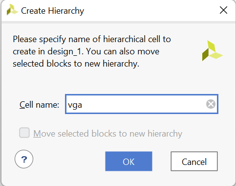
Create a Hierarchy named vga.
Add the Digilent IP library folder to Project Settings\IP\Repository (see earlier link).
Open the vga hierarchy and add the follow IP:
Dynamic Clock Generator (Digilent)
Configure the AXI Video Direct Memory Access
Change Frame Buffers to 2
Verify Enable Write Channel is unchecked and Enable Read Channel is checked. For Read Channel, use Memory Map Data Width of 64, Read Burst Size of 32, Stream Data Width of 32, and Line Buffer Depth of 4096.
Set GenLock Mode for the Read Channel Options to Master
Configure the Video Timing Controller
Deselect Enable Detection
On the Default/Constant tab, I selected 1080p, but I don't think this matters, as it gets set from MicroBlaze.
Configure the AXI4-Stream to Video Out
Change FIFO Depth to 32
Set Clock Mode to Independent
Set Timing Mode to Master
Configure the Slice
Change Din From to 23
Configure RGB to VGA output
Set Blue, Green, and Red color depth to 4
Create the following Pins in the vga hierarchy
vga_red, Output, vector from 3 to 0
vga_green, Output, vector from 3 to 0
vga_blue, Output, vector from 3 to 0
vga_hsync, Output
vga_vsync, Output
Create the following Ports in the Block Design (not within the vga hierarchy)
vga_red Output, vector 3 to 0
vga_green, Output, vector 3 to 0
vga_blue, Output, vector 3 to 0
vga_hsync, Output
vga_vsync, Output
Make connections as seen in the image below
Regenerate the layout


In the Block Design, add the MicroBlaze IP.
From the Board tab in the Block Design, double-click DDR3 SDRAM. Choose to connect it to mig_ddr_interface.
Disconnect the clk_ref_i pin on the Memory Interface Generator (MIG 7 Series). You can delete the clk_ref_i port. Connect the clk_ref_i to ui_addn_clk_0.
Run Block Automation. Choose New Clocking Wizard for the MicroBlaze Clock Connection.
Run Connection Automation, selecting All Automation with default values.
Delete the Utility Vector Logic and reset port.
Connect the Clocking Wizard reset to the ui_clk_sync_rts of the Memory Interface Generator (MIG 7 Series). Configure Clocking Wizard. Flip the CLK_IN1 to sys clock and back to Custom. Change EXT_RESET_IN to Custom. Click OK. Connect the clk_in1 pin of the Clocking Wizard to ui_clk of the MIG.
Run Connection Automation and say OK to defaults.
Configure the MicroBlaze memory in the Address Editor. Set dlmb to 256K and ilmb to 128K.
I find a UART to be helpful for debugging. If interested, add an AXI Uartlite IP to your Block Design and Run Connection Automation. Choose All Automation and default values. I typically set Baud Rate to 115,200 in the IP Configuration for the AXI Uartlite.
Delete the diff_clock_rtl port.
Connect aclk to vid_io_out_clk on the AXI4-Stream to Video Out.
Validate the Block Design to confirm there are no errors at this point.
Create an HDL wrapper for the Block Design.
Generate Block Design. I find that Vivado typically fails to generate the design on the first attempt. Do not continue until you have successfully generated the design (check Design Runs). If necessary, cancel and restart the generate block design.


Add a constraint file to the project and set the following:

I usually Reset Output Products of the design and re-generate the block design at this point to verify the IP is cached.

Regenerate Layout. You should have something similar to this:

Run Synthesis
Run Implementation
Generate Bitstream
Export Hardware, Include bitstream
In Vitis, choose Create Application Project. In the New Application Project wizard, choose Create a new platform from hardware (XSA) and browse to the previously-exported hardware file (e.g., design_1_wrapper.xsa).
On Application Project Details, give the project a name and leave other values at defaults. On Domain, leave defaults. On Templates, I usually select Memory Tests.
In the new project, open memorytest.c and rename the main() function (e.g., to main_old()).
Copy Russell's sample files from zybo-vga/software at master · RTSYork/zybo-vga (github.com) into src (for now, copy vga_example.c and the zybo_vga folder; do not copy vga_example_anim.c -- this can get used later).
In vga_example.c, change line 27 (DisplayInitialize) to:
DisplayInitialize(&dispCtrl, XPAR_AXIVDMA_0_DEVICE_ID, XPAR_VTC_0_DEVICE_ID, XPAR_VGA_AXI_DYNCLK_0_S_AXI_LITE_BASEADDR, pFrames, FRAME_STRIDE);Also, on line 33, change the &VMODE to &VMODE_640X480. Update lines 13 and 14 accordingly.
Comment out lines 38-40 (printf), or replace printf with xil_printf.
Create a new linker script and place the Data Sections in DDR (mig_7series_0_memaddr).
Connect the VGA Pmod to JB and JC.
Connect to the Arty via USB and program the device.
Run the Vitis project.


The output will be running at 640x480 @ 60 Hz. If you would like to try 800x600, update lines 13, 14, and 33 to reference 800x600.

If 800x600 works for you, you could experiment with higher resolutions. You may need to modify the clock setup to go much higher. I quickly tested 1280x1024 @ 60 Hz, and it worked fine. Of course, it was slower to paint a frame.

If you're successful up to this point, you could try out animated content. Try out Russell's vga_example_anim.c sample. Here's a modified version of Russell's animated example that I had previously tested.
Project Files
I have posted the complete Vivado and Vitis projects used in this walkthrough to my GitHub.
Questions I Have
While the clocking works in this configuration, I expect I have made mistakes in connecting all of the different clocks. If you have suggestions, please let me know. I need to learn more about the different clocks.
Is there a better memory configuration to use? It might be better to have the frame buffer in BRAM, but I couldn't figure out how to fit it in BRAM on the Arty A7-100T.
How else can I improve this build?
I hope you found this walkthrough helpful!

Comments