
Arty A7 & OLEDrgb Pmod Walkthrough
- rehsd

- Nov 11, 2021
- 4 min read
Updated: Dec 6, 2021
My first attempt at getting Digilent's OLEDrgb Pmod working with an Arty A7 was unsuccessful. After a fair amount of troubleshooting and experimenting, I was able to get the Pmod to work. Following is a walkthrough of the steps that ultimately led to a working display for me.
Disclaimer: While these steps may have worked for me, you will want to make sure you validate anything listed here prior to implementing on your system. If you have suggested updates to this posting, please let me know.
Starter References
The following articles were helpful in getting me started.
The Hardware
I am using a Digilent Arty A7-100 (XC7A100TCSG324-1). The Pmod is a Digilent OLEDrgb.
Setting Up the Software
I am running Windows 11 (Version 21H2 build 22000.318).
I am using Vivado 2021.2, along with Vitis 2021.2. To install the Xilinx software, I ran the Xilinx Unified Installer 2021.2 (Web Installer). I chose to install the Vitis Unified Software Platform (Vitis, Vivado, and Vitis HLS), support for 7 Series (Artix-7 specifically), and the Cable Drivers. For reference throughout this walkthrough, I installed Xilinx software on my D:\ drive.
I installed the Digilent board files (the set specific for Microblaze). The board file folders were extracted into D:\Xilinx\Vivado\2021.2\data\boards\board_files.
I downloaded the latest XDC files.
Building the Vivaldo Project
Create a new project in Vivaldo. Add the appropriate XDC file for your board. Choose your board on the Default Part screen.


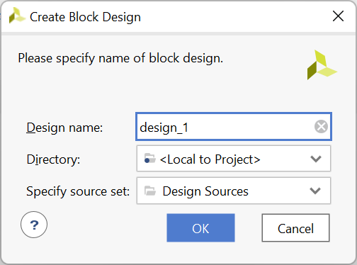
Create a Block Design


Add IP and choose MicroBlaze


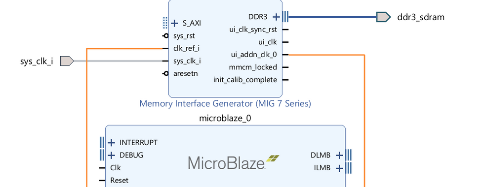
In the Board window, right-click DDR3 SDRAM and choose Auto Connect.
Delete the clk_ref_i clock signal.
On the Memory Interface Generator (MIG 7 Series), connect ui_addn_clk_0 to clk_ref_i.


In the Sources window, open Constraints and modify the constraint file (.xdc) for your board. Uncomment the two clock signal lines and change the name from CLK100MHZ to sys_clk_i. While you're in this file, you may also want to add the following lines for voltage settings.
## Voltages
set_property CONFIG_VOLTAGE 3.3 [current_design]
set_property CFGBVS VCCO [current_design]
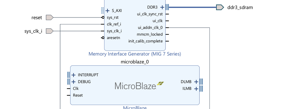
In the Block Design Diagram, click Run Connection Automation and click OK in the Run Connection Automation dialog.


Add IP and choose Clocking Wizard.
Click the Regenerate Layout button to rearrange the diagram.
Connect ui_clk on the MIG to clk_in1 on the Clocking Wizard.
Connect reset on the Clocking Wizard to ui_clk_sync_rst on the MIG.


Double-click the Clocking Wizard. On the Output Clocks tab, check clk_out2 and set it to Requested Output Frequence of 50. Choose OK.

(I then clicked the Regenerate Layout button again.)
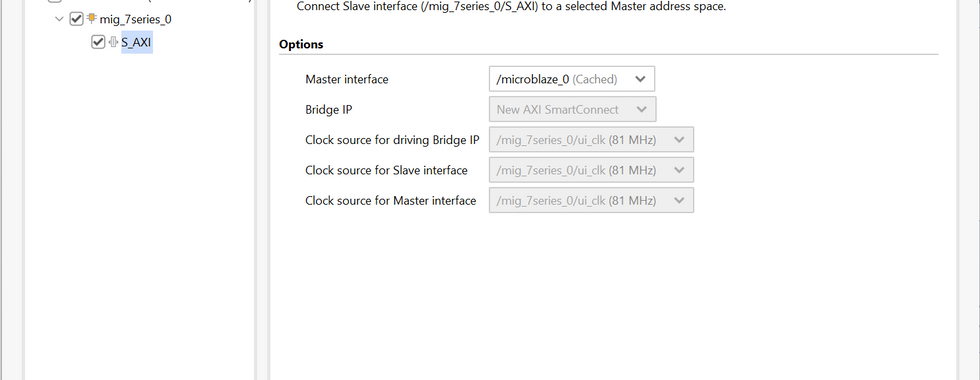
Click Run Block Automation.
Local Memory: 64KB
Cache Configuration: 16KB
Clock Connection: /mig_7series_0/ui_clk (81 MHz)
Click Run Connection Automation and choose OK.


Download the Digilent IP library and extract the files.
From Project Manager, choose Settings. Under Project Settings, go to IP, Repository. Click '+' to add. Navigate to where you extracted the Digilent IP library and choose it. Click Select, OK, OK.


From the Board window, double-click Connector JA under Pmod. Choose PmodOLEDrgb_out and click OK.

Click Run Connection Automation, check all, and click OK. (I then clicked the Regenerate Layout button again.)


Delete the clock connection between the Clocking Wizard clk_out1 and PmodOLEDrgb_v1.0 ext_spi_clk. Draw a new connection from the Clocking Wizard clk_out2 to PmodOLEDrgb_v1.0 ext_spi_clk.

Double-click the MicroBlaze and deselect "Use Instruction and Data Caches" and choose OK.

Might be good to Save at this point, if you haven't been saving along the way.
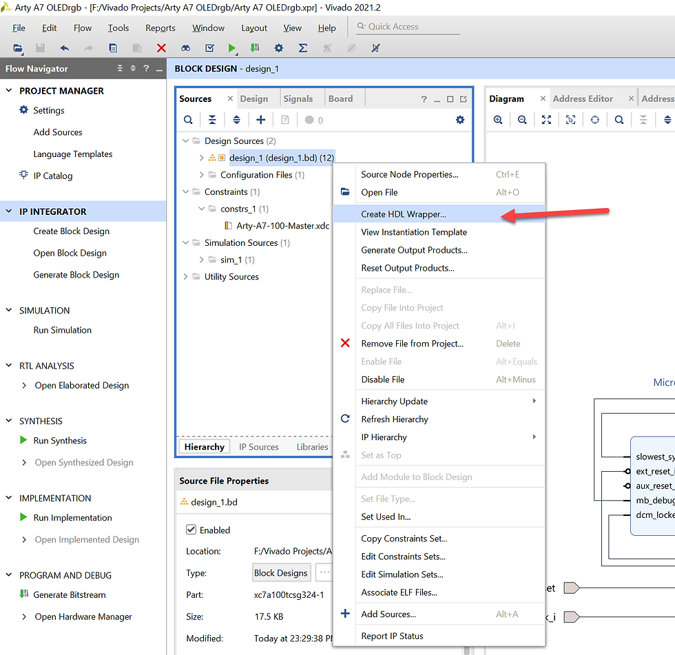
From Sources, right-click on your design under Design Sources and choose Create HDL Wrapper. Choose Let Vivado manage wrapper and auto-update, then click OK.
In the Flow Navigator on the left, under Program and Debug, click Generate Bitstream. Save if prompted. If prompted, click Yes to automatically start implementation. Choose OK on Launch Runs.
You may receive three critical warnings due to versioning of the board and Pmod. If so, choose OK on the warning dialog and let synthesis complete running. When the block runs fail, choose Reports, Report IP Status from the top menu. Verify all items show Up-to-date. If any do not, you can check them and select Upgrade Selected. On my system, while I got the initial error, when I viewed the IP status, they were updated and no further action was required.

I then chose Validate Design from the Block Design Diagram. If prompted to rerun as it's already in a valid state, choose Rerun Validate Design. Launch Generate Bitstream again.
One issue I run into regularly is error "[Common 17-165] Too many positional options when parsing..." To resolve this, I simply delete the .dcp file in Sources\Utility Sources\..\Design Checkpoint and disable incremental synthesis. I imagine a more appropriate fix is needed (but I don't know what that fix is at the moment). If you get this error like I do, delete the .dcp, change the Incremental synthesis setting, and try the Generate Bitstream again. Note: I later found out this was due to my project folder name containing a space. I removed all spaces from the directory structure, and I no longer encounter this issue.

You should now be at the point of successfully generating a bitstream. On the Bitstream Generation Completed dialog, choose Cancel. Choose File, Export, Export Hardware.


At this point, we are ready to move to Vitis.
Building the Vitis Project
After exporting the hardware from Vivado, choose Tools, Launch Vitis IDE.

Choose Create Application Project, then Next on the welcome screen.
Select Create a new platform from hardware (XSA), choose Browse to select the hardware file you previously exported from Vivado, and choose Next.
Provide an application name (no spaces) and choose Next.
Choose Next on the Domain screen.
Choose Employ Application(C) and Finish.


Copy the two example files (bitmap.h and main.c) from the design wrapper\hw\drivers\PmodOLEDrgb_v1_0\examples folder to the src folder of the standalone microblaze project.
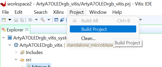
From the menu, choose Project, Build Project.
From the menu, choose Xilinx, Program Device. The defaults on the Program Device dialog should be fine. Click Program. During the configure device activity, you should see the Done LED on the Arty turn off and back on.
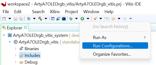
From the toolbar, click the dropdown beside the Run icon and choose Run Configurations. Double-click Single Application Debug, then Run.


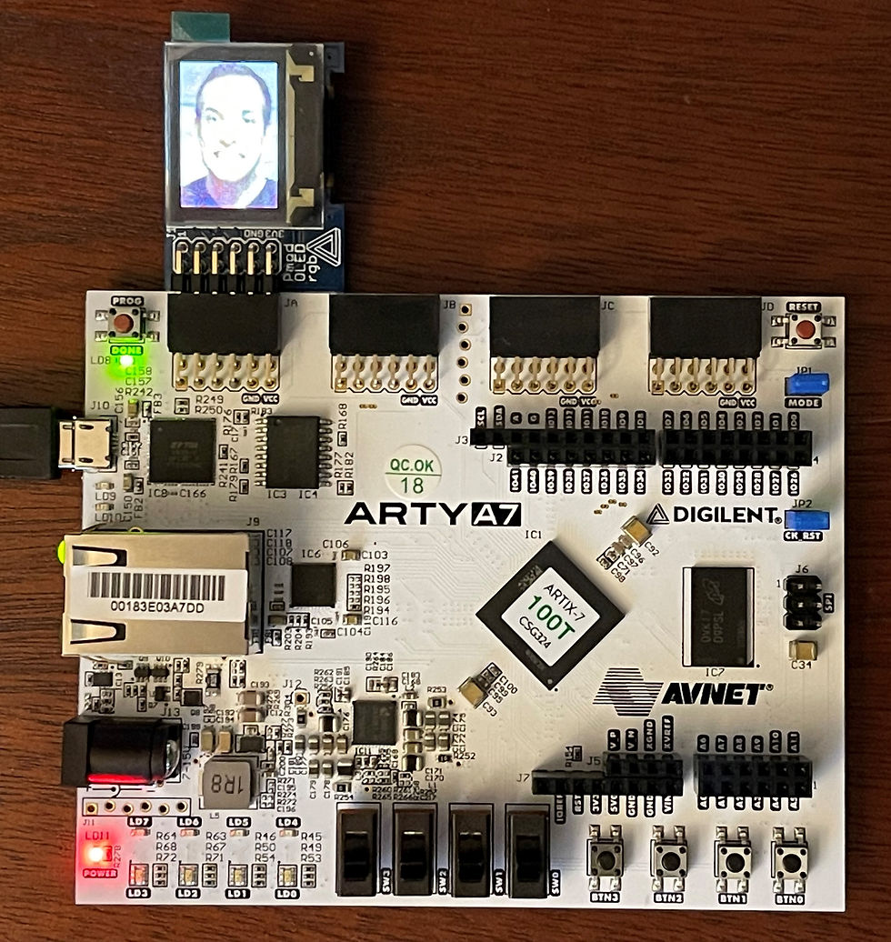
If you are successful, you should see some colored demo text appear on the screen, following by an image of (Tommy Kappenman?).

Comments