
A Start to 6502 Audio
- rehsd

- Oct 5, 2021
- 8 min read
Updated: Feb 11, 2022
What's a computer without sound?! I decided to experiment with adding sound to my 6502. I did a little research on options to add sound support, including posting the question to r/beneater. Potential options included:
I decided to try the AY-3-8910 ('8910). The '8910 is a programmable sound generator (PSG) that supports three channels of tone and/or noise. I ordered a set of inexpensive '8910s from Ebay. (While I've seen posts about some of these chips being fake or non-functional, the set I received turned out to work fine.) In addition to the datasheet, I found a copy of the data manual; this turned out to be very helpful.

The '8910 has 8 data lines (DA0-DA7) and 16 IO lines (IOA0-IOA7, IOB0-IOB7). The data lines are used to write to and read from the '8910 (e.g., to send a command to play a tone). The IO lines really aren't necessary for audio support, but could be used to connect a joystick or ROMs for audio data. The '8910 also has clock and reset lines, along with a couple of address lines (A8, A9B). Three additional lines are used for control: BC1, BC2, and BDIR; these lines are used to indicate the current function: inactive, read, write, or latch address. Then there are 3 analog outputs.
With a basic understanding of the '8910, I decided to connect a pair of '8910s to a VIA. I used two '8910s so that one could cover the left audio output and the other right audio output. This would let me have stereo output with 3 subchannels (A, B, C) each. You could also easily have a mono output with 6 subchannels. I also added an EEPROM for future expansion -- to store audio data. At this point, my schematic and breadboard looked something like this:


Assembly Code
The data manual provides some assembly code examples. Also, I came across a post from cbmeeks on 6502.org. That, along with beginning to understand the different registers on the '8910 (see image below), gave me a decent feel for what the programming could look like. Basically, to control the '8910, you use the data bits to send a register address, followed by a value for that register. Those values control the output -- tone, noise, amplitude, envelope, etc.

Note: As I learned the hard way, the registers are listed in octal (I was initially trying to use the values as hex, lol, and that didn't work so well)! Thanks to u/gfoot360 for helping me realize my mistake.
I thought I'd try to get the '8910s to output a Windows XP startup sound (or something that sounded close enough to it). I looked up the sheet music and went to work. I ended up with this assembly code (sample snippets):
Sound:
    PlayWindowsStartSound:
        lda #$60
        sta delayDurationHighByte

        ;init VIA4
        lda #$FF
        sta DDR4A
        sta DDR4B

        ;init AY38910 #1
        lda #(AY2_A9_B) ;AY1_A9_B not set, therefore AY1 active
                        ;AY2_A9_B set, therefore AY2 disabled
        sta PORT4B

        ;*************** sound to AY (SND_RESET) ***************
            lda #<SND_RESET
            sta TUNE_PTR_LO
            lda #>SND_RESET
            sta TUNE_PTR_HI
            jsr AY1_PlayTune		;left
            jsr AY2_PlayTune		;right

        ;*********** sound to AY (SND_TONE_E6_FLAT_A) ***********
            lda #<SND_TONE_E6_FLAT_A
            sta TUNE_PTR_LO
            lda #>SND_TONE_E6_FLAT_A
            sta TUNE_PTR_HI
            jsr AY1_PlayTune
            jsr AY2_PlayTune
        ;*********** sound to AY (SND_TONE_F1_C) ***********
            lda #<SND_TONE_F1_C
            sta TUNE_PTR_LO
            lda #>SND_TONE_F1_C
            sta TUNE_PTR_HI
            jsr AY1_PlayTune
            jsr AY2_PlayTune
        ;*************** delay 3 ticks ***************
            jsr Delay
            jsr Delay
            jsr Delay

        ;*************** sound to AY (SND_OFF_A) *************
            lda #<SND_OFF_A
            sta TUNE_PTR_LO
            lda #>SND_OFF_A
            sta TUNE_PTR_HI
            jsr AY1_PlayTune
            jsr AY2_PlayTune
        ;************* sound to AY (SND_TONE_E5_FLAT_A) ************
            lda #<SND_TONE_E5_FLAT_A
            sta TUNE_PTR_LO
            lda #>SND_TONE_E5_FLAT_A
            sta TUNE_PTR_HI
            jsr AY1_PlayTune
            jsr AY2_PlayTune
        ;*************** delay 2 ticks ***************
            jsr Delay
            jsr Delay

        ;************ sound to AY (SND_TONE_B6_FLAT_A) ****
            lda #<SND_TONE_B6_FLAT_A
            sta TUNE_PTR_LO
            lda #>SND_TONE_B6_FLAT_A
            sta TUNE_PTR_HI
            jsr AY1_PlayTune
            jsr AY2_PlayTune
        ;*************** delay 3 ticks ***************
            jsr Delay
            jsr Delay
            jsr Delay

		...the rest of the tune...

        rts

    AY1:
        AY1_PlayTune:
           ldy #0
        AY1_play_loop:
           lda (TUNE_PTR_LO), Y
           cmp #$FF
           bne AY1_play_next
           rts
        AY1_play_next:
           jsr AY1_setreg
           iny
           lda (TUNE_PTR_LO), Y
           cmp #$FF
           bne AY1_play_next2
           rts
        AY1_play_next2:
           jsr AY1_writedata
           iny
           jmp AY1_play_loop
           rts
        AY1_setreg:
            jsr AY1_inactive     ; NACT
            sta PORT4A
            jsr AY1_latch        ; INTAK
            jsr AY1_inactive     ; NACT
            rts
        AY1_writedata:
            jsr AY1_inactive     ; NACT
            sta PORT4A
            jsr AY1_write        ; DWS
            jsr AY1_inactive
            rts
        AY1_inactive:            ; NACT
            ; BDIR  LOW
            ; BC1   LOW
            phx
            ldx #0     ;A9 high to disable AY
            stx PORT4B
            plx
            rts
        AY1_latch:               ; INTAK
            ; BDIR  HIGH
            ; BC1   HIGH
            phx
            ldx #(AY1_BDIR | AY1_BC1);  AY_A9_B low to enable AY
            stx PORT4B
            plx
            rts
        AY1_write:               ; DWS
            ; BDIR  HIGH
            ; BC1   LOW
            phx
            ldx #(AY1_BDIR) ;AY_A9_B low to enable AY
            stx PORT4B
            plx
            rts
        AY1_readdata:
            phx
            jsr AY1_inactive
            ldx #$00    ;Read
            stx DDR4A
            jsr AY1_read

            lda PORT4A
            ;jsr print_dec_lcd
            ldx #$FF    ;Write
            stx DDR4A
            jsr AY1_inactive
            plx
            rts
        AY1_read:           ; DTB
            ; BDIR  LOW
            ; BC1   HIGH
            phx
            ldx #(AY1_BC1 | AY2_A9_B)
            stx PORT4B
            plx
            rts

    AY2:	;similar to above AY1 code, but sending to AY2
		...

    WonderfulSounds:    ;)
        SND_RESET:
           .BYTE $00, $00           ;ChanA tone period fine tune
           .BYTE $01, $00           ;ChanA tone period coarse tune
           .BYTE $02, $00           ;ChanB tone period fine tune
           .BYTE $03, $00           ;ChanB tone period coarse tune
           .BYTE $04, $00           ;ChanC tone period fine tune
           .BYTE $05, $00           ;ChanC tone period coarse tune
           .BYTE $06, $00           ;Noise Period
           .BYTE $07, $38           ;EnableB   ;all channels enabled
           .BYTE $08, $0F           ;ChanA amplitude    0F = fixed, max
           .BYTE $09, $0F           ;ChanB amplitude
           .BYTE $0A, $0F           ;ChanC amplitude
           .BYTE $0B, $00           ;Envelope period fine tune
           .BYTE $0C, $00           ;Envelope period coarse tune
           .BYTE $0D, $00           ;Envelope shape cycle
           .BYTE $0E, $00           ;IO Port A
           .BYTE $0F, $00           ;IO Port B
           .BYTE $FF, $FF           ; EOF
        SND_OFF_ALL:
           .BYTE $08, $00           ;ChanA amplitude 0F = fixed, max
           .BYTE $09, $00           ;ChanB amplitude
           .BYTE $0A, $00           ;ChanC amplitude
           .BYTE $FF, $FF                ; EOF

        ;Win95 Start
            SND_TONE_B6_FLAT_A:
               .BYTE $00, $43           ;ChanA tone period fine tune
               .BYTE $01, $00           ;ChanA tone period coarse tune
               .BYTE $08, $0F           ;ChanA amplitude max
               .BYTE $FF, $FF           ; EOF
            SND_TONE_A6_FLAT_A:
               .BYTE $00, $4B           ;ChanA tone period fine tune
               .BYTE $01, $00           ;ChanA tone period coarse tune
               .BYTE $08, $0F           ;ChanA amplitude max
               .BYTE $FF, $FF           ; EOF
            SND_TONE_E6_FLAT_A:
               .BYTE $00, $64           ;ChanA tone period fine tune
               .BYTE $01, $00           ;ChanA tone period coarse tune
               .BYTE $08, $0F           ;ChanA amplitude max
               .BYTE $FF, $FF           ; EOF
            SND_TONE_E5_FLAT_A:
               .BYTE $00, $C8           ;ChanA tone period fine tune
               .BYTE $01, $00           ;ChanA tone period coarse tune
               .BYTE $08, $0F           ;ChanA amplitude max
               .BYTE $FF, $FF           ; EOF
            SND_TONE_B3_FLAT_C:
               .BYTE $04, $18           ;ChanC tone period fine tune
               .BYTE $05, $02           ;ChanC tone period coarse tune
               .BYTE $0A, $0F           ;ChanC amplitude max
               .BYTE $FF, $FF           ; EOF
            SND_TONE_E3_FLAT_B:
               .BYTE $02, $23           ;ChanB tone period fine tune
               .BYTE $03, $03           ;ChanB tone period coarse tune
               .BYTE $09, $0F           ;ChanB amplitude max
               .BYTE $FF, $FF           ; EOF
            SND_TONE_A2_FLAT_C:
               .BYTE $04, $B3           ;ChanA tone period fine tune
               .BYTE $05, $04           ;ChanA tone period coarse tune
               .BYTE $0A, $0F           ;ChanC amplitude max
               .BYTE $FF, $FF           ; EOF
            SND_TONE_F1_C:
               .BYTE $04, $2F           ;ChanC tone period fine tune
               .BYTE $05, $0B           ;ChanC tone period coarse tune
               .BYTE $0A, $0F           ;ChanC amplitude max
.BYTE $FF, $FF ; EOFNote: As I write this, the latest version of my ROM code is available here (look for the Sound: label).
Up to this point, I had a working circuit that could output sound. User u/gfoot360 raised the idea of adding a summing amplifier for the output. I thought that was a good idea. I tried to do this with an LM358 op amp, but ultimately, I didn't like the quality of the audio output. I switched to a pair of LM386 power amplifiers. The output of these sounded good and looked good on the oscilloscope. My goal was to have a strong line-level output that was referenced at 0 V (i.e., no DC bias). That got me to the following circuit. R33 through R36 were left in to keep the levels low enough for line-level output. I have the LM 386s set at the minimum 20x gain (they can go up to 200x).

This is what the output looked like on the oscilloscope:


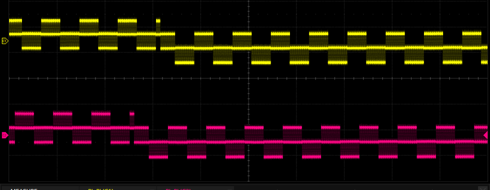

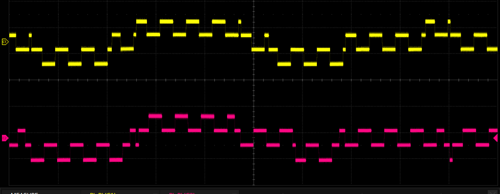


In the output, notice that the left and right channels are slightly out of phase with each other. I'm pretty sure this is simply due to how I'm setting the channels from assembly code, and the time the 6502 takes to process one command for a channel and then get to the next command for the other channel.
Along the way, while working on the LM386 output, I accidentally connected the analog output directly to the 10 Ω resistor, bypassing the 0.47 μF capacitor. This led to some slight melting of my breadboard. Oops... :( You might also notice I have a diode after the 10 Ω resistor. Without the diode, when I grounded both left and right channels, I was picking up a local radio station. I suppose this could have been an extra feature of my design -- built in AM/FM radio. While the diode took care of the issue, I suspect there is a better solution (I don't know what it is though).

I learned that the YM2149 is a direct drop-in alternative to the '8910. I ordered a set and swapped out my '8910s. Everything worked and sounded the same (at least I couldn't notice a difference). You can listen to both in the video posted further down.

I added a pair of LED 10x bar graphs to show output signal levels for left and right channels, using a pair of LM3915 display drivers. The LM3915 drives the LEDs based on analog input. With the LM3915, individual resistors are not needed with the LEDs, and I thought this was a really convenient way of showing output levels.
Below are the full schematics for my 6502 audio, a picture of the breadboard circuit, and a short demo video. In the video, the first half is using the '8910, and the second half is using the YM2149.


So Much More to Be Done
I see plenty of opportunity to improve my design and build upon it. Some things that come to mind:
Reduce any phase delays between the left and right channels. I don't think this is noticeable, but I'm curious to see if I can improve it.
Free up A9B to VIA connections. Currently, I am using A9B as a programmable "enable" to switch between the two '8910s. This might not be necessary, and I might be able to leverage BC1 and BDIR to accomplish my goal of having two '8910s on the same data bus from the VIA. Testing to be done.
Develop more complex sounds, music, and audio effects with tones and noise.
Leverage the dedicated EEPROM for audio data. Currently, the EEPROM is there, but I'm not using it. For the time being, I'm using my 6502's EEPROM to store sound data.
See if I can store and playback VGM files. Numerous, fun examples are available at VGMRips.
Spin a PCB version of the audio portion of my overall 6502 system.
Well, that's probably enough for this first installment on 6502 audio. I've learned a great deal already about 6502 audio, but I know I'm just scratching the surface.
Postscript
I am using a 5 MHz clock for my 6502 and a 2 MHz clock for the '8910s. If your setup uses different clock speeds, you will need to adjust things like delay durations, tone frequencies, etc.
While I am connecting my '8910s to a VIA, you could also consider connecting the '8910s directly to the 6502 data bus, removing the VIA from the equation. Possibly, I can try this in the future.
Comments